Startechcom IES51000 Instrukcja Użytkownika
Przeglądaj online lub pobierz Instrukcja Użytkownika dla Akcesoria komputerowe Startechcom IES51000. StarTech.com IES51000 User Manual Instrukcja obsługi
- Strona / 12
- Spis treści
- BOOKMARKI
Podsumowanie treści
Manual Revision: 08/15/2014For the most up-to-date information, please visit: www.startech.comDE: Bedienungsanleitung - de.startech.comFR: Guide de l&
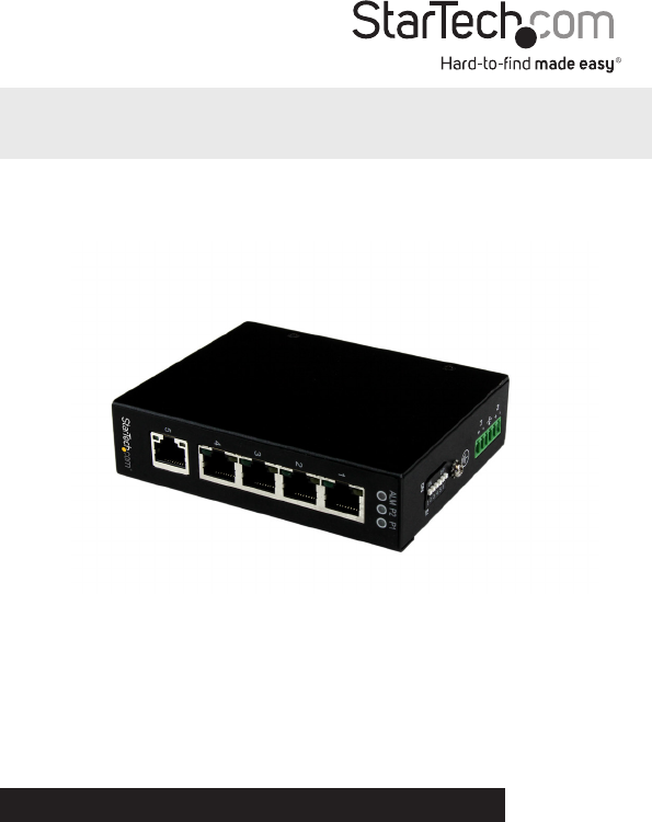
Instruction Manual7SpecicationsNumber of Ports 5Compatible Networks 10/100/1000 MbpsIndustry StandardsIEEE 802.3 10BASE-T, IEEE 802.3u 100BASE-TX, IE
Instruction Manual8Technical SupportStarTech.com’s lifetime technical support is an integral part of our commitment to provide industry-leading soluti
Hard-to-nd made easy. At StarTech.com, that isn’t a slogan. It’s a promise.StarTech.com is your one-stop source for every connectivity part you need.
Instruction ManualFCC Compliance StatementThis equipment has been tested and found to comply with the limits for a Class A digital device, pursuant to
Instruction ManualiTable of ContentsIntroduction ... 1Packagi
Instruction Manual1IntroductionPackaging Contents• 1 x Industrial Ethernet Switch • 2 x Wall-Mount Brackets• 1 x DIN-Rail Clip • 4 x Screws• 1 x
Instruction Manual2Top ViewLED Indicators1 x P1 (Power)Solid (Green): Power is connected and functioningO: No power input detected1 x P2 (Power)Solid
Instruction Manual3DIP Switch SettingsInstallationThe Network Switch is designed to sit on a at surface, or be securely mounted to either a wall or D
Instruction Manual42. Determine the desired location and orientation of the switch on the wall, and mark the bottom mounting notch location.3. Dep
Instruction Manual5DIN-Rail Mounting1. Attach the DIN-Rail mounting bracket to the switch. 2. Hook the unit over the DIN-Rail and push the bottom o
Instruction Manual6Hardware Installation1. Ground the device using the ground screw.2. Power the switch from a DC power supply (input range 12 – 58V
Powiązane produkty i podręczniki dla Akcesoria komputerowe Startechcom IES51000
 (11 strony)
© 2020, manymanuals.pl. Wszelkie prawa zastrzeżone. | 0.066 s |
 Manymanuals.com
 Manymanuals.de
 Manymanuals.fr
 Manymanuals.it
 Manymanuals.pl
 Manymanuals.cz
 Manymanuals.es
 Manymanuals-pt.com
Komentarze do niniejszej Instrukcji